Call-to-Mail Forwarding

This project aims to redirect an incoming phone call to an e-mail address, without any third-party services, the entire system running locally.
Essentially telling the person what they need to do to contact you by other means. A similar thing can be done using phones when it goes over to voicemail, however it is not dynamic and harder to update.
What we want here is an easily updatable, zero-effort, understandable messages when someone calls. While keeping it extendable for future projects, like making something comparable to Google Duplex.
While these are my goals for this particular project, the techniques can be applied to achieve a variety of automated phone projects.
The total cost of a single one-off board is about 15$ and can be put together in an hour. The software used is free (libre) and can also be put together pretty quickly. You do need a PC or a fast SBC for the software, so keep that in mind.
NOTE: This project is currently in progress and subject to change
Introduction
Why?
If you have a company or public facing contact information, you might get some spam calls. Or maybe you just prefer mail over calls, because of it being asynchronous. Either way you will probably want to redirect people to your mail while still being 'discoverable' through a phone number.
Generalizing
Although this project has the intent of forwarding calls to an mail address this can be used to tell the caller any information.
With this project you could potentially make an alternative to Google Duplex, but self-contained.
Features
- Pass information to callers
- Receive incoming audio as 'voicemails'
- Real-time high quality TTS
- Somewhat portable
Electronics
We will be using the SIM800L module to do our GSM/GPRS bidding, because it's cheap and easy to use with minimal external components.
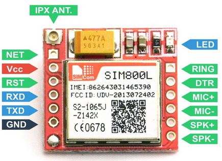
Let's look at what we have to work with.

Power Supply
We have Vcc, GND, RST for power.
The SIM800L runs on 3.4-4.4V which is sadly just out of the range of an standard USB power of 5V. So a step-down converter is needed to get it to the appropriate voltage.
We will use an LM2596 to achieve this, it's slightly overkill, but does the job and allows for other power sources later on. It will step 5V down to 3.9V to get the optimal voltage for our SIM800L.
According to the SIM800L datasheet it has an continuous energy consumption up to 500mA with peaks at 2A. This is convenient as it's the max rating of USB 2.0+ devices, which means this device should work almost anywhere.
The RST pin can be pulled down (for 100ms) to reset the chip in case it's bricked, we will add a button here, just in case.
Serial Interface
We have our RXD and TXD for Serial.
We need Serial to, among other things, detect and accept incoming calls.
The SIM800L uses AT codes (also Hayes commands) to communicate with external chips, these are a set of relatively standard commands used in telecommunication.
For a full list of commands see the datasheet.
For now we are only interested ATA (Accept call), ATH (Hang up). As well as an incoming RING message for incoming calls.
We can use these to automatically accept an incoming message, wait for however long your scripted audio message takes, and hang up.
Audio Interface
We use Mic+-/ SPK+- for analog audio I/O. These can simply be connected to any audio source/sink, in this case a PC or SBC.
For the Mic you want to make sure your signal is around 1.7V as the maximum rated input is 2.2V (which is easy to breach).
Putting it all together
Our SIM800L runs on max 4.4V, while our SBC (or PC USB terminal) probably runs on 5V. This means that if try to connect the two together it would fry the SIM800L, so we need to fix that.
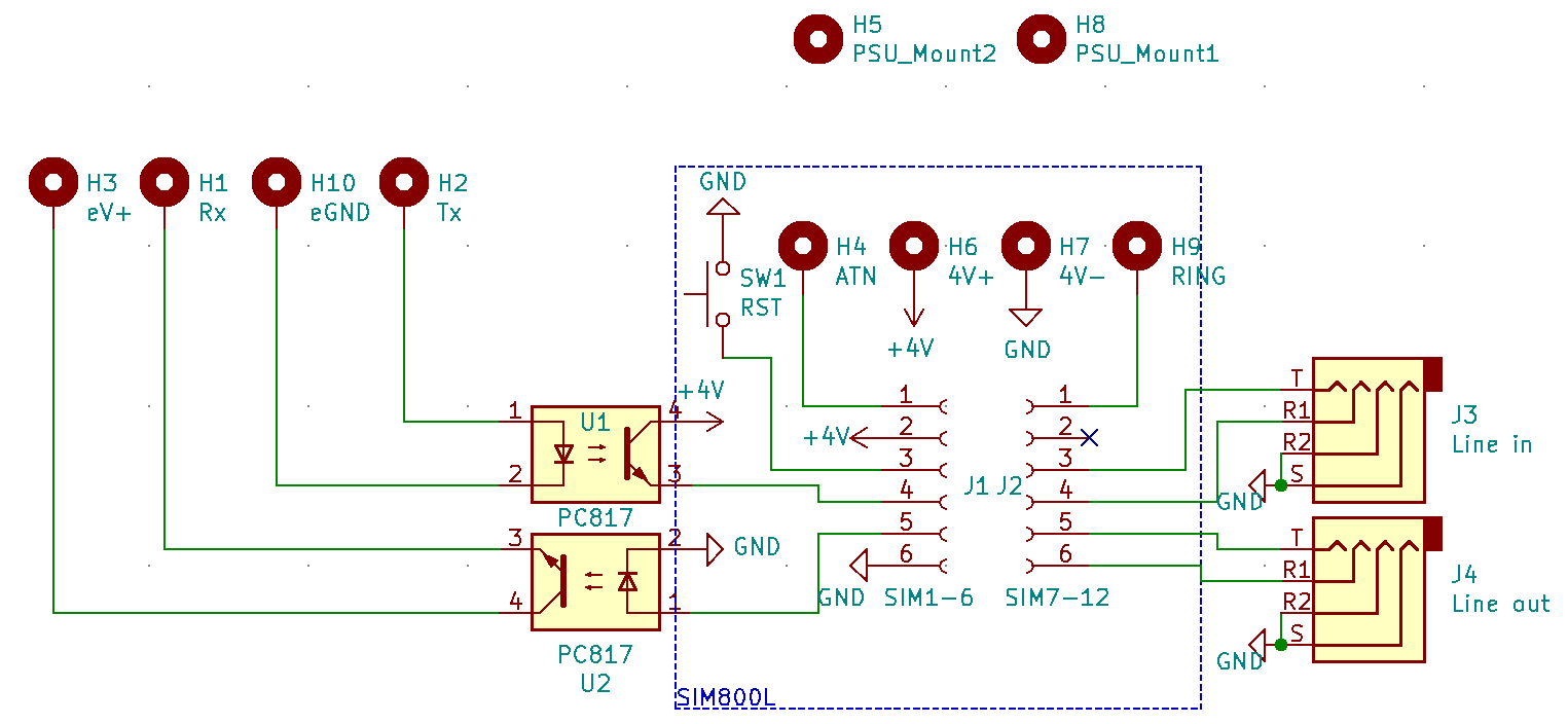
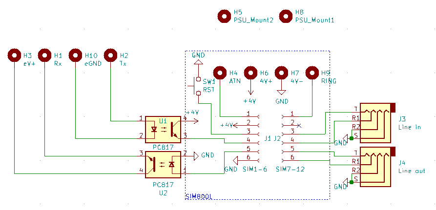
We can connect them optically, which means each circuit electrically isolated but is able to transfer signals. These components are appropriately called optocouplers. Optocouplers are usually pretty cheap, especially in bulk. You can use a dual-channel/bidirectional optocouplers, but in our design we just use 2 single-channel unidirectional couplers.
We will also be soldering each module (except PC/SBC) to our own PCB so we have a single board to worry about. Further we will be using 4-pole audio jacks for our mic/speaker.
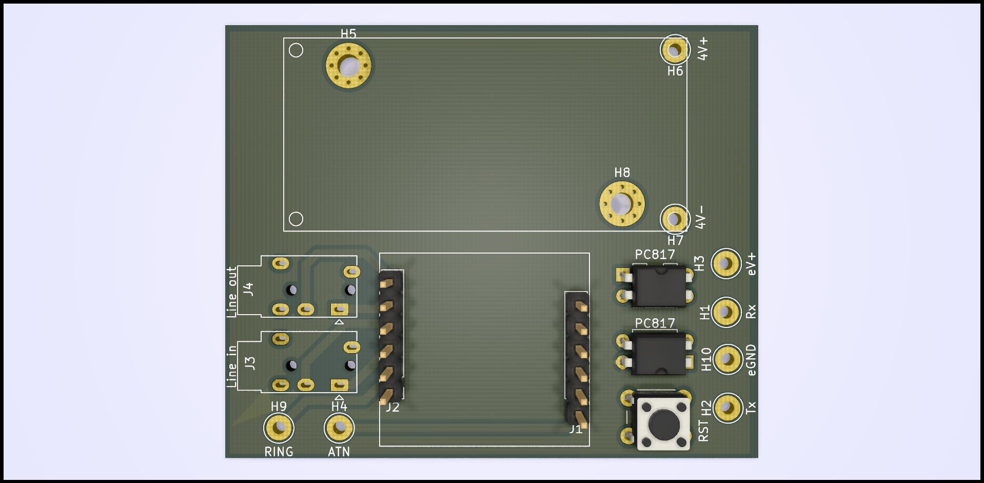
Here is the resulting PCB (KiCAD files will be available soon):


In total the cost of the complete PCB with modules is about 15.13$. Do note that this would be a lot cheaper when scaled up, as about 70% of that is either shipping costs or minimal order quantity limits.
| Component Type | Cost($) |
|---|---|
| 10x PC817 | 1.39 |
| 1x SIM800L | 2.50 |
| 1x LM2596-Module | 1.20 |
| 10x PJ320E | 2.19 |
| 100x 6mm switch | 0.85 |
| 5x Custom PCB | ~7.00 |
| Total | 15.13 |
TTS Generation
Ideally we run the complete system on something like an Raspberry Pi 3B. However we also need to consider the TTS, if you want it to generate in real time you need either a fast model or a fast GPU.
You can see how we achieved that here: https://blog.devdroplets.com/real-time-organic-tts/
Further reading
Electronics:

TTS Models:


